Tuesday, May 18, 2010

Fire Fighting Robot [Video]

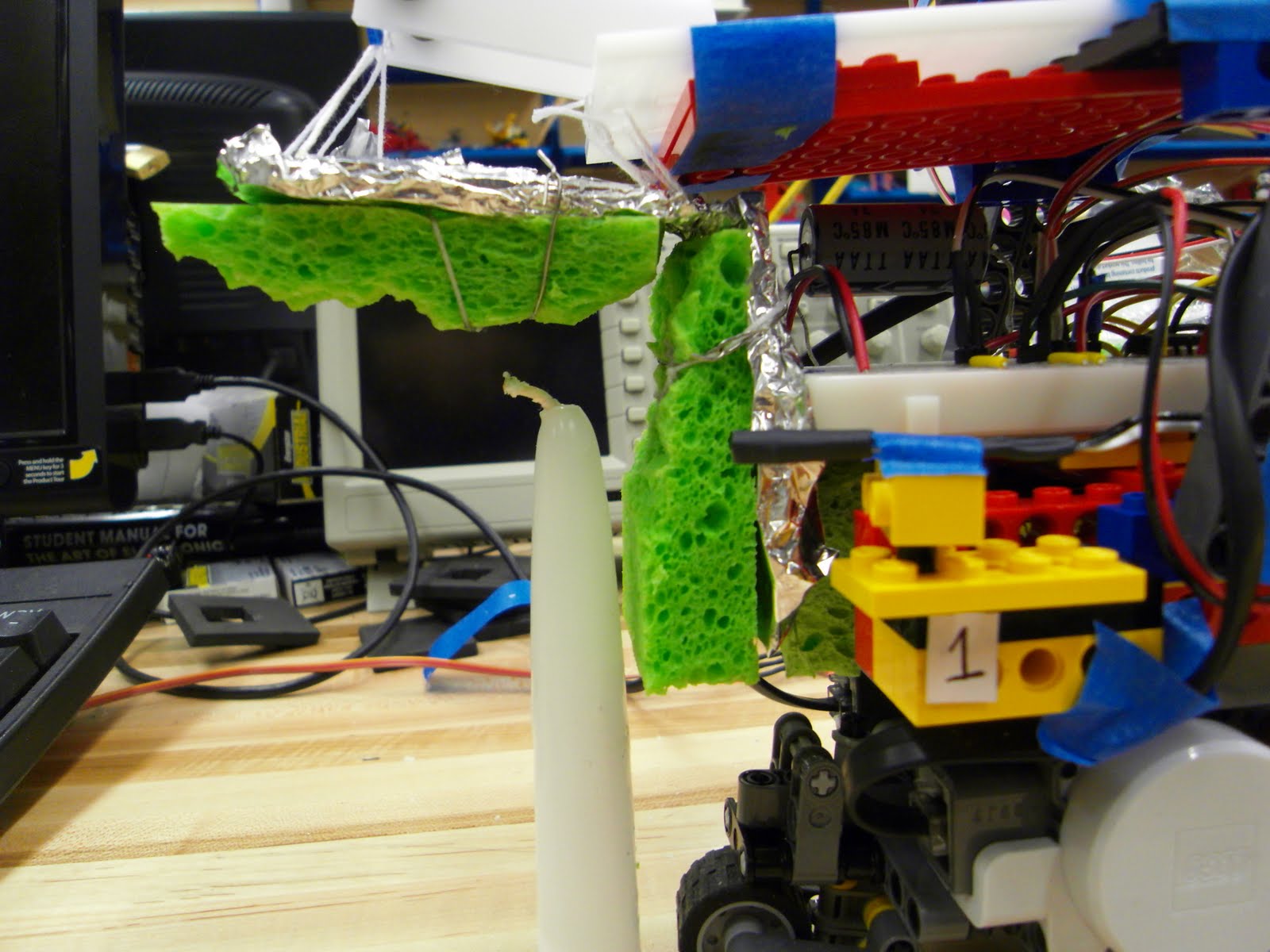
[Fire Fighting Robot: Video - 10 ft Distance, Finding & Putting Out the Candle]


This was one of our first tries on our fire fighting robot. It was able to find and locate the candle to the position where it needs to be in order for the top shell to squiz it down. The only problem with it was that it did not really put out the fire. We came to a solution that adding some forward and backward movement when the top sea shell is over the candle would really put the light out.

[Fire Fighting Robot: Video - Finding the Candle]


After the first tryout, we decided to implement some codes so that the robot can move slightly forward and backward with the top shell over the candle, so that the light gets extinguished. In this video, we have added such methods. The robot finds the candle and moves towards it, but did not fully get to the candle. We checked on our sensor readings after and, for some reason, they have changed from what they used to be in front of a candle. Anyways, it was designed to repeat the hello method (the method that drops the top shell, moves slightly forward and backward [to put out the candle light completely] and then bring the top shell back up) with some forward movement each time until the light was out. We, however, had to stop the robot because the strings were almost on fire. But, we were happy that the robot found the candle and placed it right in the middle of the two sensors.

[Fire Fighting Robot: Video - Finding the Candle with More Precision]


We fixed the sensor values by a little bit to be more precise this time. The robot found the candle, almost perfectly stopped at the position where it was supposed to and executed the hello method to drop the top shell and put out the fire. However, the robot decided to behave weirdly even though we did not touch any other code. It would just move forward with full power all the sudden, when there wasn't code like that. Lia and I did not have any idea why, and we now are supposing that the offM method possibly is the problem because our last code to this tryout was offM method. It also was supposed to repeat the hello method if the light was still on. Hmm... weird... I wish I had known what the problem was.

[Fire Fighting Robot: Video - Finding & Putting Out the Candle]


After a few try outs, we found out that our car actually consistently finds the candle without trouble, moves towards it and positions itself so that the candle is in between. The only part that we thought we needed to work on was the ending, when the top shell drops and tries to extinguish the light. The candle lights were stronger than we expected. So here is a video of our robot extinguishing the candle light with slight forward, slight left, slight right and then slight backward movement to really put out the candle. And it works so well! We were so happy!!!

[Fire Righting Robot: Video - 10 ft Distance, Finding the Candle]


Right after we had success with the code above, we tried to show Lyn our new mechanism. However... we had the similar problem that we had before with the second video above. Our robot just had decided to act weird and just move forward. We did not change a single code after the video above. After then, our hello method stopped working appropriately and we no longer were able to control our servo motor, which was really sad... But we are happy with how far we have come with the project and the outcomes!

Fire Fighting Robot [Coding]

[Fire Fighting Robot: Coding - Auxiliary codes]


There are 12 auxiliary methods. I call them auxiliary because they do not really control the motion of our robot, but either start or help the mechanism:

* brake, forward, backward = Those methods make the robot behave like their names
* lslow, rslow, sback, sfor = These methods are abbreviation for "left slow," "right slow," "slow backward" and "slow forward" (They are controlled by the low power settings from input)
* nudge = Nudge allow the car to march forward for 100 msec each time invoked
* settee = If the reading from sensor 1 is greater than the given value of the variable largest, then it sets the largest to whatever value read from sensor 1.
* getlarge = This method helps the settee method. It allows the car to turn left one full rotation and help settee method set the value of the variable largest to be the reading from sensor 1.
* startpos = This method determines the starting position and is invoked after the getlarge method. By the time this method is invoked, the variable largest will be set to the values read from the sensor 1 during the one full rotation. The robot turns left until the sensor 2 detects a number 100 less than the given largest value. (100 was a good number for it to stop facing the candle. If the number was too small, then the value of largest was often bigger than the reading from sensor 2, causing the robot to just spin and spin)
* FINAL = This method is what we double click to give all the instructions to our robot.

[Fire Fighting Robot: Coding - Main code "go-d-2" & "hello"]


This method called "go-d-2" is the method that commands the robot to travel a certain distance in the beginning. Once it gets close to the target line (10 feet away from the start position), it starts to check for the light. Generally, our readings on sensors were pretty consistent. They would always range in between 993-996 if the candle was in the desired position (in between the two sensors and under the top shell). Therefore, we set our if condition to be "if sensor 1 reading if less than 990," which means that the candle is not in our desired position. If the if statement is true, then the snud2 method gets invoked (snud2 method basically commands the robot to approach the candle so that it is in the desired position. It is explained in greater detail below). Otherwise, it would perceive the condition as "yes, the candle is in the right place" and would brake and then execute the method called hello.

The hello method is the one that controls the mechanism of the servo motor and, therefore, the mechanism of the top sea shell. In the beginning, we only had the servo motor turn thisway, wait for a while, and then turn thatway, causing the top sea shell to drop down, squiz the candle, and the go back up. However, many of the times, the light on candle would not go out completely and would light up again after the sea shell goes up. Therefore, we implemented some more mechanism to our hello method to really make sure that the candle light goes out. We added sfor, lslow, rslow, and sback methods, which were invoked after the top sea shell has dropped, having the candle light in between the two sea shells. With it in between, the robot would move slightly forward, left, right and then back. In this way, the robot completely put out the fire without a question. (This is also shown in one of the video clips in the next blog entry)

[Fire Fighting Robot: Coding - Main code "snud2"]


This method is our really long method. It gets invoked from the go-d-2 method to begin with. Under the condition that the sensor 1 reading is less than 990, which means that the robot still has to search for the candle, this method commands the robot to move towards the candle based on the difference between sensor1 and sensor2 (difference = sensor 1 - sensor 2). A positive or a value that is greater than 5 for the difference means that the candle is placed to the left of the robot since sensor 1 is on the left side of it. So, it would be commanded to execute lslow method or left slow method. We also wanted to have another if condition before executing lslow method because the candle may be really close to the robot and so commanding it to turn left can be suicidal for the robot. Therefore, in the method above includes another if statement that checks if the sensor 1 reading is greater than 990. If it is true, then we surely want to back up and then execute lslow method. If the difference is a negative number or a number that is less than -5, then we want to do the opposite and the same logic was applied to the coding. If the difference is fairly small, which means that the candle is pretty much in between the two sensors, then the robot is to be commanded to nudge forward.

In the beginning, we refrained ourselves from using the other two sensors, sensors 3 and 4, because we believed that they were making the coding even more complicated than it already was. However, because we had our sensors 1 and 2 angled slightly inward, the sensors were reading numbers very unexpectedly as it got closer to the candle light. When the light was placed in front of sensor 2 (on the right), sensor 1 (on the left) was reading a greater number than sensor 2 because of the shadow created from the black cover we put on the sensors. And this caused our motor to turn the other direction, again, setting itself on fire. Therefore, we decided to use the readings from sensors 3 and 4 in the beginning of the method. If the back sensors were reading larger number than the front sensors, then we had the robot turn to the side of the sensors. In this way, the robot no longer turned to the other direction.

After this method, the system will return to the forever loop in the go-d-2 method and repeat the whole process again.

Fire Fighting Robot [Design]

[Fire Fighting Robot: Design 1]


This model was our first design for our fire fighting robot. As we have decided to use wet sponge to put out the candle light, we attached some sponge onto the two shells using some strings and wires. We were concerned about the weight because we were anticipating the possibility of the strings breaking or the servo motor not being powerful enough to pull the shell up. However, thankfully, neither of our anticipation came to be true. The sponge, even though wet, was not that heavy, and our servo motor was powerful enough to sustain the weight of wet sponge. We made the surface of the sponge rough by cutting parts of it so that the sponge can really push down onto the candle light. We also covered parts of the shells by foil to make sure that nothing burns down. The ideal height of a candle was approximately 4 inches for our robot.

[Fire Fighting Robot: Design 2]


This is our second model for our model. After several try outs, we discovered that our robot would find the candle, but would miss it by 1/5 of an inch, which is a huge distance for our mechanism. The robot really had to be right in front of the candle because putting a candle out with sponge, unlike many would think, was not so easy. Even after our robot pushed out on the candle, the light would not extinguish completely and revive again. So, our thought was that if we have a wider sponge area for the robot, then even if it missed the candle by a little bit, it wouldn't matter because the sponge is now wider. However, attaching some more pieces to the sides of the center sponge was not a good idea because it kept on falling. It also continuously covered the sensors' light reading, which caused a huge problem in our mechanism.

[Fire Fighting Robot: Design 3]


Besides the unsuccessful result from the fire fighting robot design 2, the robot got itself on fire during one of the tryouts. As a result, the 4 strings holding the top shell piece were all burnt down and everything was a mess. However, after a few hours of repairing, we were able to restore all the ruined parts. To not get it on fire EVER again, we decided to cover every parts exposed to the dangers of fire with aluminum foil.

After we threw away the idea of widening our sponge pieces, we needed to come up with a better scheme to put out the candle light reliably. We decided to polish on our code and make the robot move slightly forward, slightly left, slightly right and then slightly back, during which the top shell will stay down. This is better explained in the video section with some cool video clips :) Anyways, our Design 3 model is the final design that we decided to stick with.

Fire Fighting Robot [Setup, Modeling, SolidWorks]

[Fire Fighting Robot: Setup]

For our fire fighting robot, we implemented four sensors, two on each side. Sensors 1 and 3 are on the left side of the robot, while sensors 2 and 4 are on the right of the robot. Sensors 1 and 2 are the front sensors. Sensors 3 and 4 are the back sensors. We also added some Lego parts on top of our MotorCar so that we could attach to-be-cut delrin parts of our design later. We also had the servo motor hooked up to our Lego chip all ready to go!


[Fire Fighting Robot: Modeling]

We made our ideas into a model using the foams and basing on the sketches we had. The pictures below show our model. The top shell would have six holes in total, four in the front and two in the back. The four holes in the front help keep the balance of the top shell piece when up in the air, hanging from the string. The back two holes allow the top shell piece to be hanging from the base piece.


We knew that pinching the candle light in between the two delrin cut pieces would not extinguish the candle light but rather would start a fire. So, after a few hours of brain storming together, we came up with the idea of using a wet sponge in between the shells. Thanks to Lyn, he was able to get some colorful and pretty sponge for our robot!

[Fire Fighting Robot: SolidWorks]

Here are the three pieces for our fire fighting robot. They were to be cut from delrin, using the laser cutter, so we produced them in SolidWorks. They are exactly how we envisioned them in sketches, although the sea shell piece does not really look like a sea shell. Printing the parts out, we encountered some difficulties. Our first try was a failure because it printed the tiny stars in SolidWorks sketches. Also, it cut the lines that were different from the drawing (especially for the sea shell piece). We found out that it was because the sketches were either under-defined or over-defined (it showed red and gray lines for outlines of our drawings). We fixed the problem just by re-defining every dimensions, using smart dimension. Then, we were finally able to get our parts printed out!

Monday, May 17, 2010

Fire Fighting Robot [Sketch]

[Fire Fighting Robot: Sketch]


My partner and I wanted to create a sort of a squizzing mechanism to put out the candle. In the process of brain storming we came up with the idea of a bird wings. The wings would be up in the air hanging (connected to the servo mortor) and once the MotorCar finds the candle, the two wings would come together and squiz the candle in between. However, we knew that it would require much power from the servo motor, which we were not sure how powerful was. Therefore, we decided to have one wing stay still and have the other wing move down and up to put out the candle.


The image above illustrates the idea of just using one wing, whose one end is attached to the servo motor hanging. It would travel the 10 feet hanging up as high as possible, and once the candle is placed in between the two wings, the servo motor would spin and drop the hanging wing. In order for the wing to drop reliably, we needed a supporting piece that would allow the hanging wing to come up vertically and not diagonally. Therefore, we decided to make a supporting piece that would stick out from the top of the MotorCar. This is shown in the lower right corner of the picture above.


I personally did not like the idea of side ways wings because it would look just weird. Birds fly forward and it would look so awkward if we made our design into a side way bird opening up and down only its one wing. Therefore, we decided to make our design into sea shells. The sketch above is a distorted sea shell design to fit the width of our MotorCar. So, the top and bottom of the sea shell would squiz the candle in between. The second picture is a simplified version of it. It has two small circular holes on the top. They are the string holes to connect it with the base piece.


The two images above are the remaining parts of our mechanism. The top picture is the base that will be placed on top of our MotorCar. It has two small circular holes and two rectangular holes. The circular holes will be used to hang the top sea shell, and the rectangular holes are where the supporting pieces (the bottom picture) will be puzzled in. There is a circular hole in the supporting piece for the teflon rod to go through. The string connecting the bottom end of the top sea shell and the servo motor will rest in between the supporting pieces. Therefore, we designed the holes in the supporting pieces to be tight fits.

Thermal Systems [Part 3]

Proportional Control

Lia and I worked on the MATLAB proportional control. We experimented it by using the heater on MotorCar and by simulation. It was interesting to see the similarities and differences in our simluation and experimented results. We used 20, 5, and 2 for the gain to be used in our system. With each gain, the system reached the target temperature differently.

Below are the experimental results of the system with the gain of 0.5W/K, 0.2W/K, and 0.05W/K. We found the system with the gain of 0.2W/K to be optimal because it reached the target temperature gradually without much oscillation. The system with 0.5W/K was provided too much power in the beginning and, as a result, it overshoot the target temperature. The system with 0.05W/K was not supplied with enough power to reach the target in the given time. (Also, it is interesting to note the unexpected dot plotted on our 0.5W/K graph. We do not know how it happened, but it happened!) We have submitted our deliveries to the Conference Drop Folder, and there should be all of our results for simulations for those systems.


Proportional and Integral Control

I found this exercise very interesting, maybe because I like the word "proportional" as I have explained in my blog entry for the MotorCar proportional control. With the gain that we found optimal in the previous exercise (gain = 5 in the units of our system), we were able to experiment the proportional integral control.

Here is the result of our experimentation on proportional integral control. In the beginning, full power is being supplied to the system to bring up the temperature to the target temperature. Once it reaches the target temperature of 340K, the power drops to near 0 to not over shoot the target. As time passes, there is more fluctuation in power setting because of the Law of Cooling. I just found it invigorating how the system adjusts its power setting proportional to the temperature or the error (target state - present state). It is amazing how the temperature is being kept almost constant at the target temperature throughout the time interval!


We also have the simulation of our Proportional integral control in the Conference Drop Folder. (I am only discussing about our experimental results here because they are more interesting!)

Sunday, May 16, 2010

Thermal Systems [Part 2]

MATLAB Simulation of the Heating

For the thermal challenges, we first had to calculate the physical constants of the heating system. In order to do so, we had to get a graph (temperature vs. time) of our thermometer in the process of heating up. Here is the graph that we used to calculate the constant.


To calculate C, we used the interval between time=20 and time=40 because there weren't much fluctuation and, therefore, was more reliable than the other. Also, because we were told to do so. Here is the equation we used to calculate C:

Change in temperature = 20 degrees
C = heat capacity = dE/dT
dE = P * dt = 6.48 * 20 = 129.6
C = 129.6 / 20
C = 6.48


To calculate Rth, we used the whole interval for change in temperature and applied the values to the equation below:

dT = 80 degrees
Rth = dT / dE
dE = P = 6.48
Rth = dT/dE = 80/6.48
Rth = 12.34


Below is our graph of simulation heatsim.m.


We believe that the simulation agrees almost with our experimental results in that it starts and end in similar places and that it has the similar curve to it. However, we found that when we saw some delay in the beginning of our heating system in experiment, the simulation did not. Right off from the beginning (intervals from time=0 to time=20), the temperature continued to rise without any delay.

Bang-Bang Control

The image below shows our graph to simulation for Bang-Bang Control:


The image below shows our graph to experimental results to Bang-Bang Control.


Our implementation was different from the simulation in that it had gentler oscillations and gradual changes in slope each time.